Ohm's Law
SC 130 Physical Science laboratory twelve centers on Ohm's Law relating voltage, current, and resistance. The laboratory has been using equipment that dates back to the Community College of Micronesia (CCM).

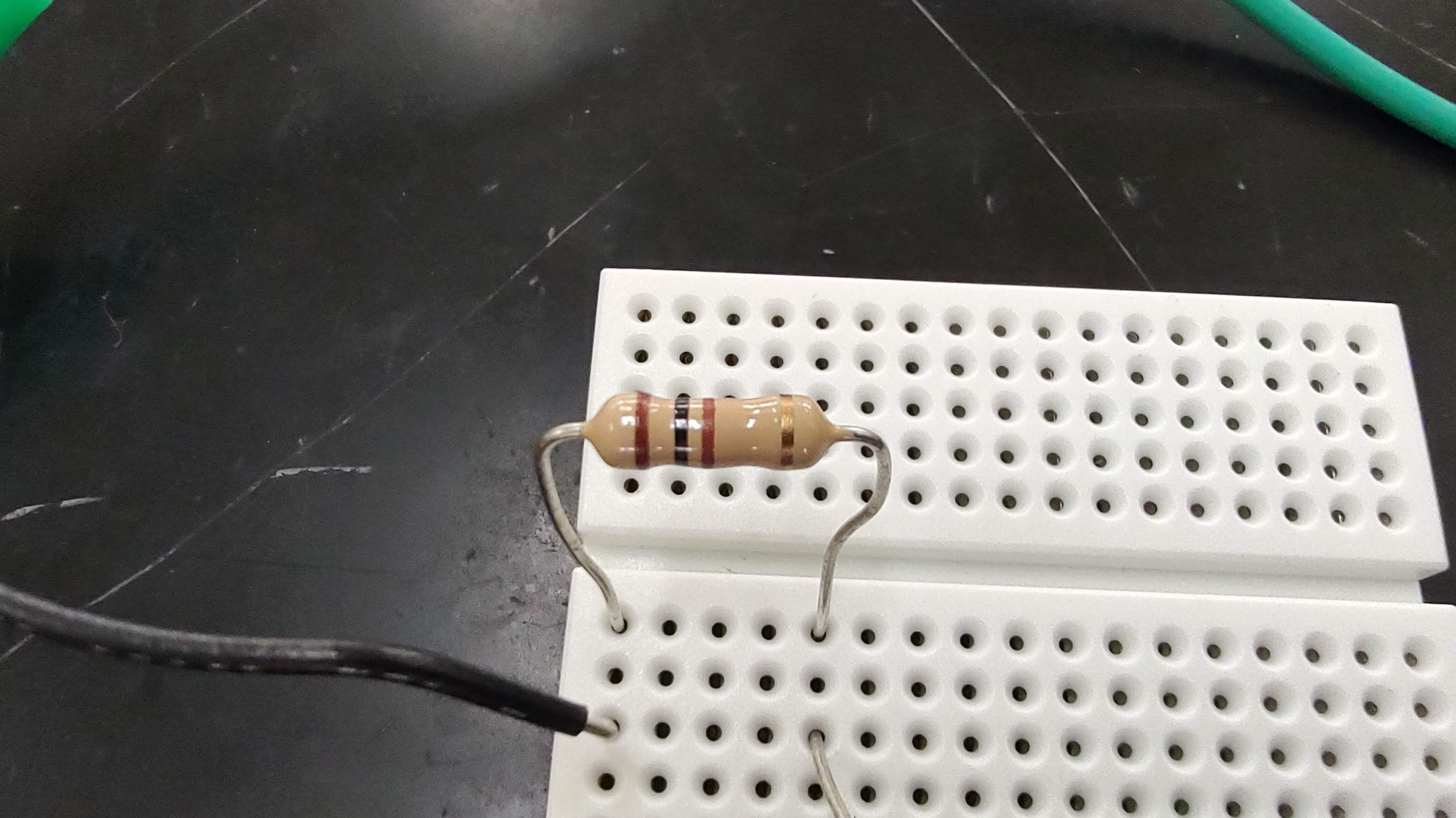
With thanks to the team that supports the course at the college, the Ohm's law laboratory now uses multimeters, circuitry breadboards, and banded resistors.

One of the educational drawbacks to the CCM equipment is that the decade resistance box is not a component that is used in electronics. The decade resistance box was designed and built for classroom use. Students do not get exposed to the color band system for resistors nor do they even see a resistor. The new laboratory uses a circuitry breadboard as would be used in electronics design, and actual resistors with color bands. This makes the laboratory more authentic and more reflective of equipment actually used in the electronic industry.

I deliberately chose not to set up the laboratory in advance. I wanted the students to work with the new equipment directly from the packaging the equipment came in. As this would be the first run of the laboratory on new equipment, I took some pictures of the students at work. Above A-Ann and Marmayon use a diagram seen on the right to set up their Ohm's Law circuit. To simplify the circuit I swapped out the potentiometer for the use of a changeable number of batteries. The new battery holders facilitate this approach as they snap together to create cells in a series.

Cordny opted to tackle the far more complex circuit with the potentiometer. On the right can be seen a resistor color band chart. Here he adjusts the potentiometer to vary the voltage in the circuit.

For the potentiometer based circuit Cordny chose to use a 330 Ohm resistor. The use of 100 Ohm and 330 Ohm resistors meant having to use the milliamperes setting on the multimeters. This required some explanation that the values shown on the multimeter had to be divided by 1000 to get back to amperes, in other words, the decimal had to move three places to the right.

Back when the laboratory had only two complete sets of equipment I did all of the equipment set up. With enough equipment for students to work on, the students had the opportunity to engage in the set up work. Above L-Jane has learned to cut and strip #22 gauge wires while Benalyne sets up batteries for their circuit.
Using either the potentiometer, or by adding batteries, the students obtained currents through and voltages across their resistor. The result is a series of data values and plots as a linear relationship.

The students then used Desmos either on their laptop or the Desmos app for mobile devices to plot the data and find the best fit linear regression as seen above. Note that Desmos allows the student to use i for current and V for voltage, and is able to run a regression using V = iR rather than forcing the student to use y = mx. Desmos handles the reversed order on the right side automatically. Note that R² is the coefficient of determination, not the resistance of the circuit squared.
Comments
Post a Comment