Physical science class visits Kosrae Utility Authority
Get link
Facebook
X
Pinterest
Email
Other Apps
On Tuesday morning in physical science class I covered the concepts of and relationships between current, voltage, resistance, power, and energy. I also showed how one can calculate the per hour cost of an appliance using the utility rate in kilowatt-hours and the power consumed by the appliance. On Wednesday the class visited the Kosrae Utility Authority. The class wishes to thank General Manager Fred Skilling for permitting and hosting the visit by the class. Thanks are due to Casey Freddy, Gerry Protacio, and Robert Taualupe for their excellent presentations and tour. Thanks also to the support team at KUA who set up refreshments for the class. The visit was both educational and wonderful!
The class in front of one of the two 600 kW 13800 V high speed generators, all wearing hearing protection.
Tuesday I covered some of the basic terminology and Ohm's law. The lecture included coverage of how to calculate the cost for appliances. The class also toured campus making calculations for electrical devices such as a fan and an air conditioning unit.
Casey Freddy welcomed the class to Kosrae Utility Authority.
GM Fred Skilling made opening remarks including encouraging the students to pursue degrees of relevance to the work KUA does such as electrical engineering. KUA can offer scholarship support for students who study in fields of use to KUA.
The old power plant retains low speed diesels that can generate up to 1.6 MW of power. These generators produce 4.16 kV and are brought on line when either one of the newer high speed generators are being maintained. The also would provide spare capacity if peak load on the island exceeded 1.2 MW.
The new twin 600 kW generators are in another building. These output 13.8 kV and thus no transformer is needed between the generators and the feed lines.
The building, engine, and control systems were made possible by a grant from Japan.
In addition, KUA has a 200 kW solar panel grid that is attached to the Malem feed.
A second 100 kW solar panel grid is connected to the Lelu feed.
The twin 600 kW engines generate up to 1.2 MW of power. The bottom lines are the two individual generators, the top line is the total output.
Here the bottom green line is the solar contribution, the generators are the dark line above, the red line is the sum.
The reality at present is that solar only supplies on the order of 5% of the power demand.
There is a goal to expand solar capacity up to 1200 kW using areas over behind the gym and baseball field. Diesel generators would still be needed to handle load through the night and to handle power drop during the day due to rain.
The class then walked over to the workshop area. Ahead can be seen the 200 kW solar array.
Part of the 200 kW solar array. The array occupies more space than the new power plant but produces only a fraction of the power.
Mary and Elise walking over
In the workshop Operations Manager Robert Taualupe started with an equipment demonstration.
Gerry, Malia, Mary, Sina, and Renee
Mikey, Elise, Jeffan, and IC George Tilfas
One of the challenges is connecting and disconnecting high voltage systems. The switch will arc when the contacts are too close. To reduce opening and closing time, a powerful spring loaded system is used to open and close the switch. The unit makes quite a bang when the spring is released - both when opening and closing.
Robert also showed the inside of a step down transformer that brings the voltage down from 13,800 volts to the 220 volts that is fed into a household system.
The liquid is an insulating mineral oil. The oil is needed to conduct heat away from the transformer coils so the unit does not overheat in operation. Water cannot be used because water could conduct a current and lead to the unit shorting out. The three outputs are at the bottom of this image.
The class then entered the newly completed training center.
Robert explained that the three outputs on the transformer consist of a, b, and c lines. Depending on how one connects the lines there are two different 120 V phases or a single 240 Volt phase.
The transformer can deliver up to 25 kVA, 12.5 kVA on a, 12.5 kVA on b. c is the neutral line above. Suppose a lineman were to measure 30 Amps on the a line and 120 Amps on the b line. This imbalance will cause an unwanted current in the neutral c line.
The lineman also has to be concerned that the 120 Amp b line might overload that side of the transformer.
Using Ohm's law and the power relationship, written as circles above, the power on the a line can be calculated from 30 Amps × 120 Volts ÷ 1000 (to convert to kilowatts which are kVA). The power on a is 3.6 kVA, well within the 12.5 kVA limit.
The other side, however, is carrying 120 Amps × 120 Volts ÷ 1000 which equals 14.4 kVA. This exceeds the power limit for the b line. A check that the transformer is sufficient for the total load, 14.4 + 3.6 = 18.0 kVA, shows that the transformer has the capacity to carry the load ( 25 kVA capacity limit), so the solution is to move load from b over to a.
This may mean some line work to disconnect some line from the b side and reconnect them to the a side.
As an instructor there is something particularly rewarding when a class gets to see a professional at work in the field using the equations that were presented earlier in the class. This answers the question, "What does anyone do with this equation?"
The discussion during the field trip would also touch on phase angle and that the electricity is a sine wave. Phase angle is complex subject, but in this class I can have the students recall the wave form of the RipStik wheels from chapter nine as an example of a waveform out of phase: the two wheels do not have crests and troughs at the same time and place. The wheels are out of phase.
Robert then covered the power output for the 200 kW solar array. The above chart is 24 hours. During the night the panel produces no power. By day the amount of power varies according to the sun angle. Above is a sunny day.
On a rainy day, however, power output can drop both rapidly and precipitously. One of the downsides to the above chart is that the diesel generators - which are designed to run under a fairly constant load, can wind up being damaged by the rapid changes in the load as the panels "drop out" and then suddenly return on line. To smooth this out will require a very large battery unit. Kosrae will be installing a one megawatt battery system to help smooth out power delivery from the panel.
KUA bunkers 67,000 gallons of diesel. The price of power is heavily driven by the market price of diesel.
The class listens to Robert explain the the diesel bunker area.
The two transformers seen here are step up transformers from the 4.16 kV output of the low speed diesels to the 13.8 kV output of the high speed diesels.
Six cylinder high speed diesel on the left, generator on the right side.
Donning hearing protection.
(Loud!)
Group photo in front of the engine. Front row: Renee-Ann-Seshrue, Sina, Sue Malia Crystal, Judah, Elise. Back row: IC George Tilfas, CharlynRose, Mikey, Jeffan.
The engines are kept immaculately clean.
Pressure gauges.
Revolutions per minute.
The other engine and generator.
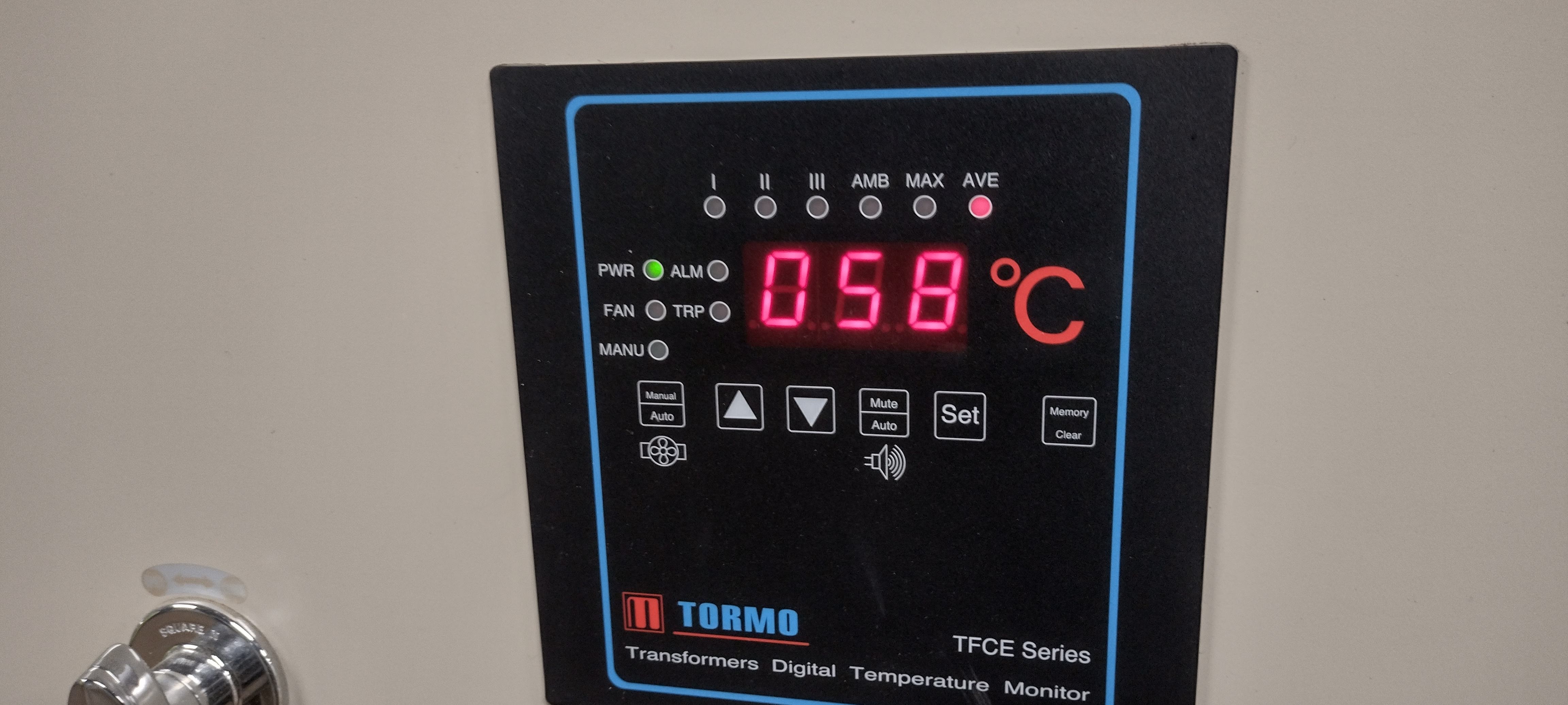
A temperature monitor.
Cabinet monitor.
Monitor on a cabinet.
One of the challenges in this climate is the humidity. The silver box at the bottom of this cabinet is a heater to reduce the humidity in the cabinet.
There is always time for a photo session.
A control panel for the number nine generator. The twin diesels are numbered nine and ten.
The leftmost top dial is displaying about 20 Amps being produced, about 500 kW (second in top row) at 13,800 volts (top right). The frequency is straight up 60 Hertz (center, second row).
Robert explaining the readouts for number ten.
Number ten readouts.
Three feeds with Tafunsak carrying the most current. Lelu and Malem are on copper feed lines, a heavier gauge aluminum is used to feed electricity to Tafunsak.
Sina inspects one of the control panels.
The new power plant building.
The three main feeds from the plant.
Malem on the left, Lelu in the center, the heavier line on the right should be the Tafunsak line.
Across the road the line join onto a single pole, the heavier line on the lower crossbeam.
The Lelu and Tafunsak lines headed up the road.
A huge thanks for the presentations, demonstrations, explanations, and tour of the facility! Truly an awesome experience for the physical science class!
Manual marking of an essay type question on a quiz or test in Moodle can be done student by student but that process involves a lot of clicking and scrolling as one has to open each student's submission. There is a bulk marking screen available. In the test or quiz click on Results. At the upper left side is a stealth drop down list menu under the word "Grades" that includes the option "Manual grading." Choose manual grading. On the far right click on the blue "grade all" hyperlink. That will open up a all of the submissions for question one on a single page. One can now mark all of the question one submissions manually for all students in the course.
The application of image recognition technologies as the back end to botany apps is providing increasingly relevant search results. Over the recent winter break I began looking at whether the apps now available might be useful to the ethnobotany class here on Pohnpei. Some apps had a more regional focus in the past and were better at north american or european plants. Pohnpei has a both unique indigenous plants and many introduced plants from around the world - a challenging environment for any image recognition system. A student working with a plant identification app for the first time My criterion was that the app had to be appropriate for use in my classroom. The app could not contain advertising and the app had to be free, my students typically do not have the ability to pay for an app. The app would also have to be fairly small as my students often use phones with limited memory and processing power. I settled on PlantNet and was impressed with the ability of the a...
The Google Statistics add-on for Google Sheets can display multiple boxplots in a single chart. The key is the layout of the data. One column should be the variable by which the data is to be grouped, the other column should be the data to be box plotted. Set up the Statistics add-on with the data to be plotted as the variable, and the grouping column as the "by" variable. In this image I had deselected all but the boxplot option, the result was the appearance of the Moment, Standard errors, and Confidence intervals options. The default is apparently a 95% confidence interval for the mean. The result is multiple boxplots on a single chart with a common scale. The new tab that is created also quotes 95% confidence intervals for the mean. Note that as of 2018 the Google Statistics add-on cannot be found by search in the add-ons. In addition, as of May 2018 the add-on no longer verifies, possibly due to the add-on not having been updated since August 2017. One may ha...


Comments
Post a Comment